MIL-PRF-23269G
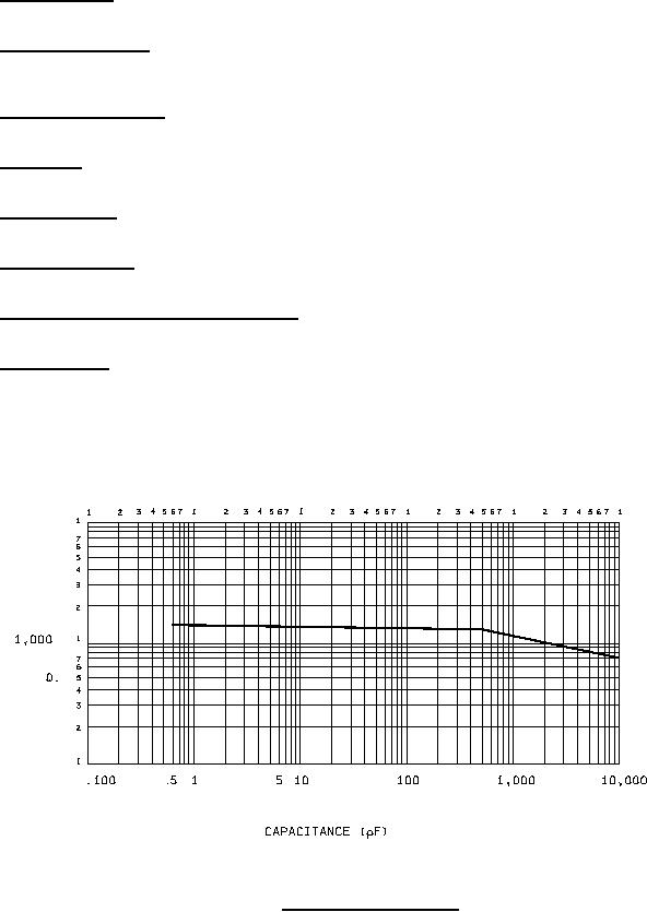
3.12 Quality factor (Q). When measured as specified in 4.7.8, the Q shall be not less than the value shown on
figure 1, unless otherwise specified (see 3.1).
3.13 Shock, specified pulse. When capacitors are tested as specified in 4.7.9, there shall be no intermittent
contacts of 0.5 millisecond (ms) or greater duration, open-circuiting or short-circuiting, or evidence of arcing or
mechanical damage.
3.14 Vibration, high frequency. When capacitors are tested as specified in 4.7.10, there shall be no intermittent
contacts of 0.5 ms or greater duration, open-circuiting or short-circuiting, or evidence of mechanical damage.
3.15 Solderability. When capacitors are tested as specified in 4.7.11, the dipped portion of the terminals shall
conform to the solid-wire termination criteria of method 208 of MIL-STD-202.
3.16 Terminal strength. When capacitors are tested as specified in 4.7.12, there shall be no loosening or
rupturing of the terminals, and no damage to the terminals or seal.
3.17 Barometric pressure. When capacitors are tested as specified in 4.7.13, there shall be no evidence of
damage, arcing, or breakdown.
3.18 Temperature coefficient and capacitance drift. When measured as specified in 4.7.14, the temperature
coefficient and capacitance drift shall be as specified (see 3.1).
3.19 Salt atmosphere. When capacitors are tested as specified in 4.7.15, there shall be no harmful corrosion or
mechanical damage, and the marking shall remain legible.
NOTE: Harmful corrosion shall be construed as being any type of corrosion which in any way interferes with the
mechanical or electrical performance of the capacitor.)
FIGURE 1. Quality factor (Q) at 1 MHz.
5
For Parts Inquires submit RFQ to Parts Hangar, Inc.
© Copyright 2015 Integrated Publishing, Inc.
A Service Disabled Veteran Owned Small Business