MIL-PRF-39001E
3.12 Solderability. When capacitors are tested as specified in 4.7.8, the dipped surface of the lead shall be at
least 95 percent covered with continuous new solder coating. The remaining 5 percent of the lead surface shall
show only pinholes or voids. These shall not be concentrated in one area. No individual view of the dipped surface
shall show less than 95 percent coverage. Bare base metal and areas where the solder dip failed to cover the
original coating are indications of poor solderability and shall be cause for failure. In case of dispute, the percent of
coverage with pinholes or voids shall be determined by actual measurement of these areas, as compared to the total
area.
3.13 Vibration. When capacitors are tested as specified in 4.7.9, there shall be no intermittent contacts of 0.5
milliseconds (ms) or greater duration, or momentary arcing, or other indication of breakdown, nor shall there be any
open-circuiting or short-circuiting or evidence of mechanical damage.
3.14 Temperature coefficient and capacitance drift. When measured as specified in 4.7.10, the temperature
coefficient and capacitance drift shall be within the limits specified in table I for the characteristic listed (see 3.1).
3.15 Thermal shock and immersion. When tested as specified in 4.7.11, capacitors shall meet the following
requirements:
a. DWV: As specified in 3.6.
b. IR: Shall be not less than 30 percent of initial requirement (see 3.9).
c. Capacitance: The capacitance change shall not exceed 1 percent or 1 pF, whichever is greater, from the
reference measurement (see 4.3.2.1).
d. DF: Shall not exceed 150 percent of the initial requirement specified in 3.11.
e. Visual examination: No visible evidence of deterioration, permanent damage to leads or case, or corrosion
on leads.
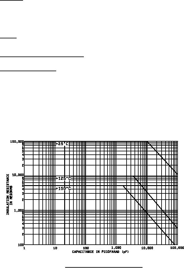
FIGURE 1. IR versus capacitance at test temperature.
6
For Parts Inquires submit RFQ to Parts Hangar, Inc.
© Copyright 2015 Integrated Publishing, Inc.
A Service Disabled Veteran Owned Small Business