MIL-PRF-123D
APPENDIX A
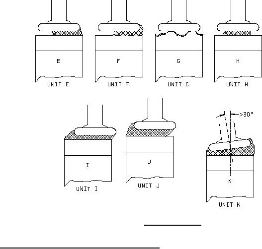
FIGURE A-3. Rejectable devices.
A.4.2 Radial leaded devices (molded) - criteria/assessment.
a. Unit M: Ideal condition for a radial leaded device prior to encapsulation. Acceptable (see figure A-4).
b. Unit N: Element thickness is greater than or equal to the average lead wire flat dimension. The element
must be positioned such that the lead wire flat does not extend more than one-third beyond the
thickness of the element. This example is rejectable (see figure A-5).
c. Unit O: Element thickness is less than the average lead wire flat dimension. The element must be
positioned such that the lead wire flat does not extend more than one-third beyond the thickness of
the element. This example is rejectable (see figure A-5).
d. Unit P: Angle between chip centerline and lead centerline shall not exceed 30° (see figure A-5).
e. Unit Q: Ideal chip alignment (top view). Acceptable (see figure A-6).
f. Unit R: If the element thickness is greater than or equal to the average lead wire flat dimension, the element
must be positioned such that the lead wire flat does not extend more than one-third beyond the
thickness of the element. If the element thickness is less than the average lead wire flat dimension,
the element must be positioned such that the lead to element interface is a minimum of 90 percent of
the available contact area. This example is rejectable (top view) (see figure A-6).
33
For Parts Inquires submit RFQ to Parts Hangar, Inc.
© Copyright 2015 Integrated Publishing, Inc.
A Service Disabled Veteran Owned Small Business