MIL-C-5G
3.3.1 Insulating, impregnating, and sealing compounds. Insulating, impregnating, and sealing compounds,
including varnishes, waxes, and the like, shall be suitable for each particular application. Compounds shall preserve
the electrical characteristics of the insulation to which applied. The compound, either in the state of its original
application or as a result of cracking or aging, shall have no adverse effect on the performance of the capacitor. The
compound shall not leak from the capacitor when it is mounted in any position under the conditions specified herein.
3.4 Interface and physical dimensions. Capacitors shall meet the interface and physical dimensions specified
(see 3.1).
3.4.1 Case. Capacitors shall be effectively sealed against the entry of moisture, and the elements shall be
mounted so as to prevent injurious movement in the capacitor cases. The capacitor elements shall be completely
enclosed by the cases except where terminals or leads project.
3.4.2 Terminal leads. Leads shall be made of a solid conductor of the length and diameter specified (see 3.1) and
shall be coated with solder, and shall meet the solderability requirements of 3.13.
3.4.3 Tin plated finishes. The use of pure tin, as an underplate or final finish, is prohibited both internally and
externally. Tin content of capacitor components and solder shall not exceed 97 percent, by mass. Tin shall be alloyed
with a minimum of 3 percent lead, by mass (see 6.7).
3.5 Dielectric withstanding voltage. When tested as specified in 4.6.2, capacitors shall withstand the direct current
(dc) potential specified without damage, arcing, or breakdown.
3.6 Barometric pressure (Qualification inspection only). When tested as specified in 4.6.3, capacitors shall
withstand the potential specified (see 3.1) without damage, arcing, or breakdown.
3.7 Insulation resistance. Unless otherwise specified (see 3.1), when capacitors are tested as specified in 4.6.4,
the insulation resistance shall be not less than the applicable requirement specified in table V.
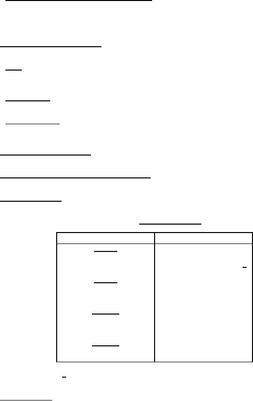
TABLE V. Insulation resistance.
Capacitance value
Minimum insulation resistance
At 25°C
0 to 10,000 picofarads
100,000 megohms
10,000 picofarads and greater
1,000 megohm-microfarads 1/
At 85°C
0 to 5,000 picofarads
15,000 megohms
5,000 picofarads and greater
75 megohm-microfarads
At 125°C
0 to 3,300 picofarads
10,000 megohms
3,300 picofarads and greater
33 megohm-microfarads
At 150°C
0 to 1,500 picofarads
5,000 megohms
1,500 picofarads and greater
7.5 megohm-microfarads
1/ Product obtained by multiplying the capacitance in microfarads
by the insulation resistance in megohms.
3.8 Dissipation factor. When measured as specified in 4.6.5, the dissipation factor shall not exceed the applicable
4
For Parts Inquires submit RFQ to Parts Hangar, Inc.
© Copyright 2015 Integrated Publishing, Inc.
A Service Disabled Veteran Owned Small Business