MIL-PRF-49464C
4.8.3.2.1 Standard voltage conditioning. Voltage conditioning shall consist of applying a minimum of twice the
rated voltage to the unit at the maximum rated temperature +4°C, -0°C for 100 +20, -4 hours. After testing, perform
measurements of 4.8.3.3.
4.8.3.2.2 Optional voltage conditioning. The manufacturer, with approval from the qualifying activity, may perform
an optional voltage conditioning test instead of the standard voltage conditioning tests of 4.8.3.2.1. All conditions of
4.8.3.2.1 apply, with the exception of the voltage applied and the test time. The accelerated condition selected for the
optional voltage conditioning shall be used for the duration of the test. At no time shall a combination of standard and
optional voltage conditioning be allowed on the same samples. The minimum time duration, T(test) minimum, shall
be calculated as follows:
Where: 2 x Erated ≤ Etest ≤ 4 x Erated
Ttest (min.)
=
800
3
(Etest / Erated)
Etest = Applied voltage
Erated = Rated voltage of the capacitor
4.8.3.3 Measurements after testing. After completion of the test, the units shall be allowed to stabilize at room
temperature (+25°C) for a period up to 24 hours. After stabilization at room temperature, the capacitance, dissipation
factor, insulation resistance and dielectric withstanding voltage shall be measured as specified in 4.8.4, 4.8.5, 4.8.6,
and 4.8.7, respectively.
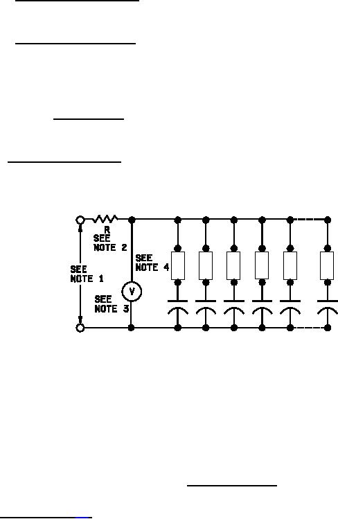
NOTES:
1. The power supply shall be capable of supplying the required test voltage.
2. The current limiting device shall be a resistor or a fuse. The current shall be limited to no less than 30
milliamperes (mA) and no more than 10 A.
3. There shall be a voltage monitor that will indicate when the applied voltage drops or increases by more than
5 percent, and shut off the test. The resistance of the voltage monitor shall be a minimum of 10X the
equivalent resistance of the series resistor and the device under test.
4. Each device under test must have a resistor or fuse in series with it. The value of the resistor shall be such
that it does not restrict the power supply's ability to provide the required test voltage to the device under
test (±5 percent).
FIGURE 2. Suggested test circuit.
MIL-STD-202. The following detail and exception shall apply:
a. Test frequencies: 1 MHz ±50 Hz for all capacitors less than or equal to 100 pF.
1 kHz ±50 Hz for all other capacitors.
b. Test voltage: A root-mean-square potential of 1.0 ±0.2 volts, when no polarizing voltage is applied.
13
For Parts Inquires submit RFQ to Parts Hangar, Inc.
© Copyright 2015 Integrated Publishing, Inc.
A Service Disabled Veteran Owned Small Business