MIL-PRF-49464C
4.8.2 Mounting for testing. When it is specified in the test procedure that the capacitors shall be mounted, they
shall be mounted on a suitable substrate (for example, 99 percent alumina). The substrate material shall be such
that it will not be the cause of, nor contribute to, the failure of any test for which it may be used. The capacitors shall
be mounted on the substrate as follows:
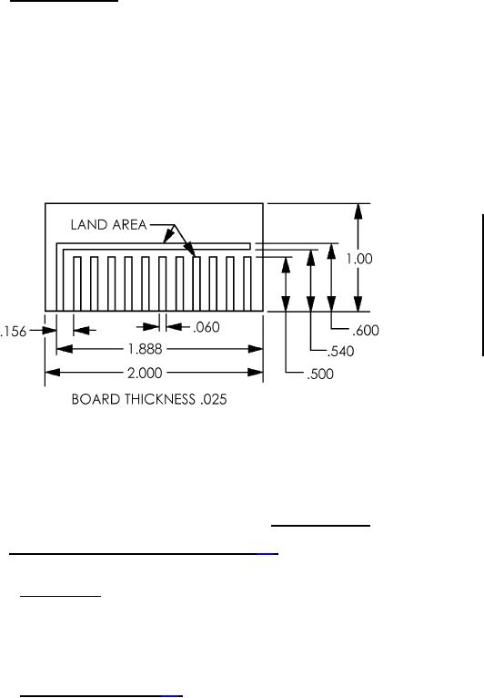
a. A substrate shall be prepared with metallized surface land areas. A typical "tests card" is shown in figure 1.
b. The capacitors to be tested shall each be attached to one land area by any convenient method (see 1.2.1.6).
c. The connection to the common land area shall begin with a thermosonic ball bond of a one mil gold wire to
the exposed capacitor terminal and end with a stitch bond on the common land area of the substrate.
Inches
mm
.025
0.64
.060
1.52
.156
3.96
.500
12.70
.540
13.72
.600
15.24
1.000
25.40
1.888
47.96
2.000
50.80
NOTES:
1. Dimensions are in inches. Metric equivalents are given for general information only.
2. The metallized land areas of the "test card" selected to facilitate testing of the chips shall be of the
proper spacing to accommodate the attachment of the applicable chips to the card.
FIGURE 1. Typical "test card".
4.8.3 Thermal shock and voltage conditioning (see 3.6). Capacitors shall be subjected to the tests of 4.8.3.1 and
4.8.3.2.
4.8.3.1 Thermal shock. Capacitors shall be tested in accordance with method 107 of MIL-STD-202. The following
details shall apply:
a. Test condition A, except that in step 3, units shall be tested at 125°C +3°C, -0°C.
b. Number of cycles: 5 cycles
4.8.3.2 Voltage conditioning (see 3.6). The intent of voltage conditioning is that all parts be exposed to a
predetermined test voltage ±5 percent, for a defined time and temperature. Voltage conditioning is done to help
eliminate infant mortality capacitors from the production lot. All parts offered for electrical testing shall be subjected to
the voltage conditioning test in 4.8.3.2.1 or 4.8.3.2.2. It shall be verifiable that all parts offered for electrical tests have
been exposed to the required voltage conditioning for the required time duration. See figure 2 for a suggested test
circuit. An alternate test circuit can be used, provided the notes of figure 2 are followed.
12
For Parts Inquires submit RFQ to Parts Hangar, Inc.
© Copyright 2015 Integrated Publishing, Inc.
A Service Disabled Veteran Owned Small Business