MIL-C-25F
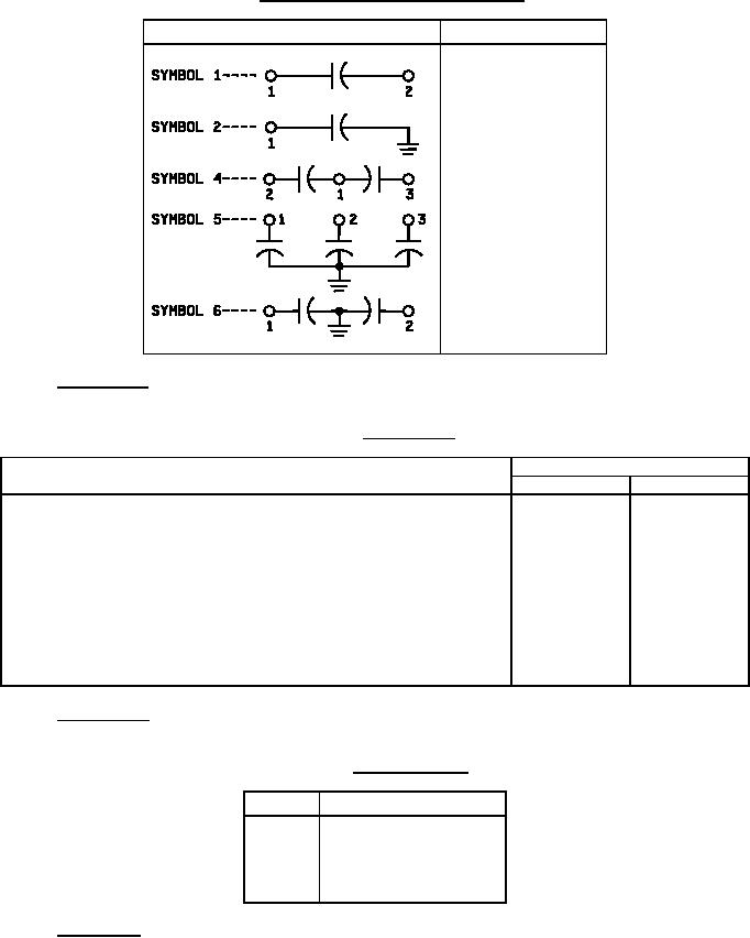
TABLE I. Circuit diagram and number of terminals.
Circuit diagram
Number of terminals
2
1
3
3
2
1.2.1.4 Characteristic. The characteristic is identified by a single letter in accordance with table II.
TABLE II. Characteristic.
Values of characteristics
Characteristic
E and F
K
High ambient test temperature, degrees centigrade ±3°C
+85°C
+125°C
Low ambient test temperature, degrees centigrade ±3°C
-55°C
-55°C
Life-test dc voltage in percent of the voltage rating at +40°C (see 4.6.15):
Watt-second group:
140
140
I:
1A (0.08 watt-second and less)
140
120
1B (0.08 + to 0.5 watt-second)
130
---
II
(0.5 + to 5 watt-seconds)
110
---
III
(5 + to 50 watt-seconds)
90
---
IV
(greater than 50 watt-seconds)
1.2.1.5 Voltage rating. The dc voltage rating for continuous operation at +40°C, except for characteristic K, which
is +85°C, is identified by a single letter in accordance with table III (see 6.9).
TABLE III. DC voltage rating.
Symbol
DC voltage rating (volts)
B
100
C
200
E
400
F
600
G
1,000
1.2.1.6 Capacitance. The nominal capacitance value expressed in picofarads (pf) is identified by a three-digit
number; the first two digits represent significant figures and the last digit specifies the number of zeros to follow.
2
For Parts Inquires submit RFQ to Parts Hangar, Inc.
© Copyright 2015 Integrated Publishing, Inc.
A Service Disabled Veteran Owned Small Business