MIL-C-25F
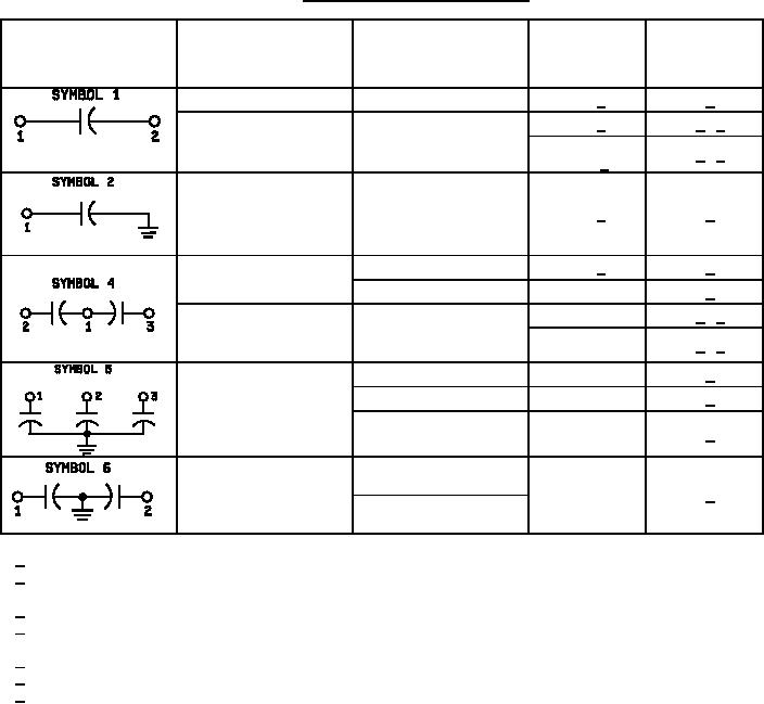
TABLE X. Dielectric withstanding voltage test.
Test voltage
Time
Test
(percent of
test voltage
Circuit diagram
Test
rated dc
connections
applied
voltage)
(minute)
Terminal to terminal
1 to 2
200 1/
1 2/
400 5/
1 3/ 4/
Terminal to case
1 and 2 to case
200 + 1,000
1 3/ 4/
volts 6/
Terminal to terminal
1 to case
200 1/
1 2/
1 to 2 and 3 together
200 1/
1 7/
Terminal to terminal
2 to 3
200
1 7/
400
1 3/ 4/
Terminal to case
1, 2 and 3 to case
200 + 1,000
1 3/ 4/
volts
1, 2, and 3 to case
200
1 7/
1 and 2 to 3
200
1 7/
Terminal to terminal
1 to 2
200
1 7/
1 and 2 to case
Terminal to terminal
200
1 7/
1 to 2
1/ 175 percent of rated dc voltage after thermal shock and immersion, and moisture resistance tests.
2/ For conformance inspection and at the option of the supplier, either 200 percent of rated dc voltage shall be
applied for 15 seconds or 250 percent of rated dc voltage for not less than 1 second.
3/ For conformance inspection, test voltage shall be applied for 1 second.
4/ For conformance inspection, applications may be made between each terminal individually and the case, at
the option of the supplier.
5/ For capacitors having dc voltage ratings of 600 volts and less.
6/ For capacitors having dc voltage ratings greater than 600 volts.
7/ For conformance inspection, the application may be made for 1 second if the capacitor has passed group A
inspection.
13
For Parts Inquires submit RFQ to Parts Hangar, Inc.
© Copyright 2015 Integrated Publishing, Inc.
A Service Disabled Veteran Owned Small Business