MIL-PRF-39014/22F
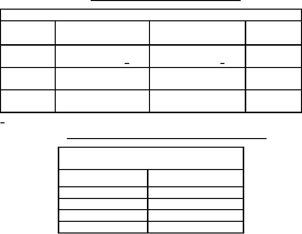
TABLE I. Dissipation factors and voltage-temperature limits.
Capacitance change with reference to +25°C
Step A through step D
Step E through step G
Dissipation
Characteristic
table VI of MIL-PRF-39014
table VI of MIL-PRF-39014
factor
symbol
Bias = 0 volts
Bias = rated voltage
(percent)
CG
0 ±30 ppm/°C
0 ±30 ppm/°C
.15
CH
0 ±60 ppm/°C 1/
0 ±60 ppm/°C 1/
.15
+15, -25 percent as
BX
±15 percent
2.5
applicable
+15, -40 percent as
BR
±15 percent
3.0
applicable
1/ See table II for capacitance values less than 20 pF.
TABLE II. Voltage-temperature limits for capacitance values of 18 pF or less.
Voltage-temperature limits for capacitance
values of 18 pF or less
Voltage-temperature
Capacitance values (pF)
coefficient tolerance
1.0 - 1.8
Not measurable
2.2 - 3.9
0 ± 250 ppm/°C
4.7 - 6.8
0 ± 120 ppm/°C
8.2 - 18.0
0 ± 60 ppm/°C
Immersion:
IR: Not less than 50 percent of initial +25°C requirements.
Resistance to soldering heat:
ĆC: ±5 percent or .25 pF, whichever is greater for CG and CH characteristics.
ĆC: +15, -5 percent of the initial +25°C measurement for characteristics BX and BR.
DF: Not to exceed the initial limit.
IR: Not less than initial +25°C limit.
Terminal strength: Method 211 of MIL-STD-202, condition B, except that each lead shall be bent away from the
body 90° from the original position (see figure 1) and back, two bends.
3
For Parts Inquires submit RFQ to Parts Hangar, Inc.
© Copyright 2015 Integrated Publishing, Inc.
A Service Disabled Veteran Owned Small Business