MIL-PRF-19978/8A
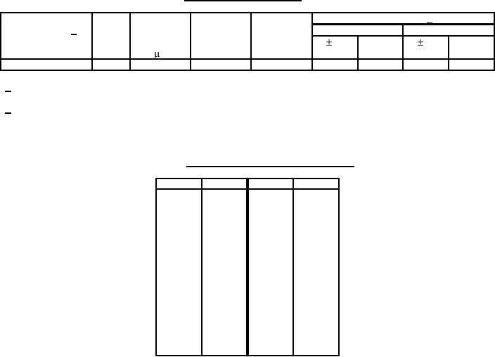
TABLE II. STYLES CQR07 capacitors - Continued.
DC
Dimensions 2/
Part number 1/
voltage Capacitance Capacitance
Failure rate
Circuit 1
Circuit 2
rating
rating
tolerance
level
L .031 D +.015, L .031 D +.015,
(Volts)
-.005
-.005
( F)
CQR07A-QF224-3-
600
.22
J, K
M, P, R, S
2.625
1.000
2.562
1.000
1/ Complete part number shall include additional symbols to indicate circuit symbol, capacitance tolerance and
failure rate level, as applicable.
2/ Dimensions are for basic case; sleeving shall extend 0.016 inch minimum and 0.062 inch maximum, beyond
each end of the capacitor body; however, if a shrink-fitted insulation is used for the sleeving, it shall lap over the
ends of the capacitor body. Add 0.047 inch maximum to the nominal for capacitance diameter.
TABLE III. Multimeter equivalent of decimal inches.
Inches
mm
Inches
mm
0.005
0.13
0.812
20.62
0.015
0.38
0.875
22.23
0.016
0.41
1.000
25.40
0.031
0.79
1.062
26.97
0.047
1.19
1.125
28.58
0.062
1.57
1.312
33.32
0.175
4.45
1.375
34.93
0.188
4.78
1.562
39.67
0.195
4.95
1.625
41.28
0.235
5.97
1.812
46.02
0.312
7.92
1.875
47.63
0.400
10.16
2.062
52.37
0.500
12.70
2.125
53.98
0.562
14.27
2.312
58.72
0.670
17.02
2.375
60.33
0.688
17.48
2.562
65.07
0.750
19.05
2.625
66.68
Custodians:
Preparing activity:
Army - CR
DLA - CC
Navy - EC
Air Force - 11
(Project 5910-2016-05)
DLA - CC
Review activities:
Navy - MC
Air Force - 19, 99
7