MIL-PRF-20M
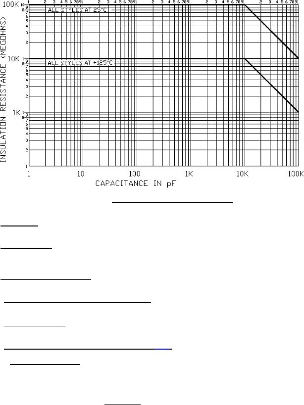
FIGURE 2. Insulation resistance versus capacitance.
3.7 Capacitance. When measured as specified in 4.7.3, the capacitance shall be within the specified tolerance
(see 3.1).
3.8 Dissipation factor. When determined as specified in 4.7.4, the dissipation factor shall not exceed the percent
specified on figure 3. Due to the limitations of measuring equipment, capacitances of less than 30 pF appear to have
a high dissipation factor, as shown in figure 3.
3.9 Dielectric withstanding voltage. When tested as specified in 4.7.5, capacitors shall withstand the dc potential
without damage or breakdown.
3.10 Barometric pressure (reduced) (qualification only). When tested as specified in 4.7.6, capacitors shall
withstand the dc potential without flashover.
3.11 Insulation resistance. When measured as specified in 4.7.7, the insulation resistance at +25°C shall be not
less than the value specified in figure 2.
3.12 Temperature coefficient and capacitance drift (see 4.7.8).
3.12.1 Temperature coefficient. Unless otherwise specified (see 3.1), the capacitor-temperature curve shall lie
within the tolerance envelope as shown in figure 1 (see 6.5). The temperature coefficient in ppm/°C can be
calculated with the following equation:
where:
C2 = Capacitance at test temperature
C2 C1
X 106
Temperature coefficient (ppm/°C) =
C1 = Capacitance at +25°C
C1(T2 T1)
T2 = Test temperature
T1 = +25°C
6
For Parts Inquires submit RFQ to Parts Hangar, Inc.
© Copyright 2015 Integrated Publishing, Inc.
A Service Disabled Veteran Owned Small Business