INCH-POUND
MIL-C-39022/9D
25 May 2001
SUPERSEDING
MIL-C-39022/9C
31 October 1973
MILITARY SPECIFICATION SHEET
CAPACITORS, FIXED, METALLIZED, PLASTIC FILM DIELECTRIC,
DIRECT AND ALTERNATING CURRENT (HERMETICALLY SEALED IN METAL CASES)
ESTABLISHED RELIABILITY,
STYLE CHR01A, CHR01B, CHR01C, CHR01D, CHR01E, CHR01F, CHR01G, CHR01H, CHR01J,
CHR01K, CHR01L, CHR01M, CHR01N, CHR01P, AND CHR01R (INSULATED)
This specification is approved for use by all Departments
and Agencies of the Department of Defense.
The requirements for acquiring the product described herein
shall consist of this specification sheet and MIL-PRF-39022.
INACTIVE FOR NEW DESIGN AFTER 31 OCTOBER 1973.
FOR NEW DESIGN, USE MIL-PRF-83421.
NOTES:
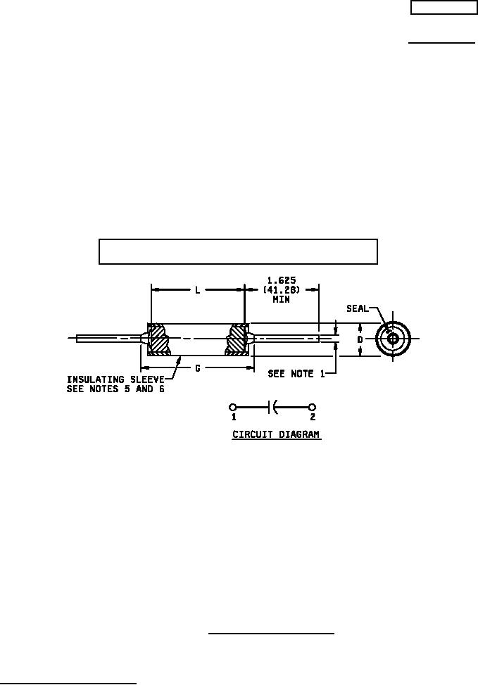
1. Number 22 AWG wire (.025 ± .002 inch (0.64 ± 0.05 mm)) for case diameters of .312 inch (7.92 mm) and less.
Number 20 AWG wire (.032 ± .002 inch (0.81 ± 0.05 mm)) for case diameters of .400 inch (10.16 mm) and
.500 (12.70 mm).
Number 18 AWG wire (.040 inch ± .002 inch (1.02 ± 0.05 mm)) for case diameters of .562 inch (14.27 mm)
and over.
2. See table I for additional dimensions.
3. Dimensions are in inches.
4. Metric equivalents (to the nearest .01 mm) are given for general information only.
5. Insulating sleeve shall extend beyond the capacitor body but shall not exceed .031 inch (0.79 mm) on either
end. Insulating sleeve thickness shall not exceed .005 inch (0.13 mm).
6. Plastic insulating sleeve shall be transparent; marking shall be applied to the capacitor case.
7. Metric equivalents are in parentheses.
8. Lead length may be a minimum of one inch long for use in tape and reel packaging, when specified in the
ordering data.
FIGURE 1. Dimensions and configuration.
AMSC N/A
1 of 15
FSC 5910
DISTRIBUTION STATEMENT A. Approved for public release; distribution is unlimited.