INCH-POUND
MIL-C-11015/18E
14 May 2001
SUPERSEDING
MIL-C-11015/18D
28 September 1970
MILITARY SPECIFICATION SHEET
CAPACITORS, FIXED, CERAMIC DIELECTRIC (GENERAL PURPOSE),
STYLE CK05
The requirements for acquiring the capacitors described herein
shall consist of this specification and MIL-C-11015.
This specification is approved for use by all Depart-
ments and Agencies of the Department of Defense.
INACTIVE FOR NEW DESIGN
after 28 September 1970. For new design use MIL-PRF-39014/1.
Inches
mm
.001
.03
.004
.10
.015
.38
NOTES:
.025
.64
1. Dimensions are in inches.
.045
1.14
2. Metric equivalents are given for general information only.
.090
2.29
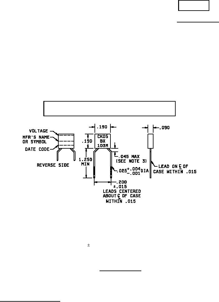
3. For flush mounting, a .078 (1.98 mm) printed-circuit hole is required to clear shoulder.
.190
4.83
4. Unless otherwise specified, tolerance is .010 (.25 mm).
.200
5.08
5. Lead length may be a minimum of .625 inch (15.88 mm) for use in tape and reel
1.250
31.75
automatic insertion equipment, when specified.
FIGURE 1. Style CK05 capacitors.
AMSC N/A
1 of 6
FSC 5910
DISTRIBUTION STATEMENT A. Approved for public release; distribution is unlimited.
For Parts Inquires submit RFQ to Parts Hangar, Inc.
© Copyright 2015 Integrated Publishing, Inc.
A Service Disabled Veteran Owned Small Business