MIL-PRF-55365/8J
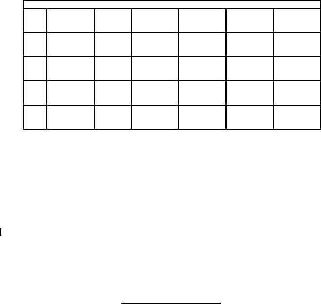
Dimensions
W2
Case
P
H2
±0.1 (.004)
L
H
W
(min)
code
±0.3 (.012)
(see note 4)
1.6 ±.2
0.7
3.2 ±.2
0.8
1.6 ±.2
1.2
A
(.063 ±.008)
(.028)
(.126 ±.008)
(.031)
(0.063 ±.008)
(.047)
1.9 ±.2
0.7
3.5 ±.2
0.8
2.8 ±.2
2.2
B
(.075 ±.008)
(.028)
(.138 ±.008)
(.031)
(.110 ±.008)
(.087)
2.5 ±.3
1.0
6.0 ±.3
1.3
3.2 ±.3
2.2
C
(.098 ±.012)
(.039)
(.236 ±.012)
(.051)
(.126 ±.012)
(.087)
2.8 ±.3
1.0
7.3 ±.3
1.3
4.3 ±.3
2.4
D
(.110 ±.012)
(.039)
(.287 ±.012)
(.051)
(.169 ±.012)
(.094)
NOTES:
1. Dimensions are in millimeters. Inch equivalents are given in parenthesis for general information only.
2. These capacitors are designed for mounting by dip or wave soldering, reflow soldering, thermo-compression
bonding, or other conventional means.
3. The anode (+) terminal shall be indicated by a marking on the case or by bevel on anode end.
4. Applicable to solderable surfaces only. The configuration of the nonsolderable area is optional.
5. Solderable surfaces are only those surfaces designated as such. Termination edges are not considered
solderable.
6. For solder coated terminations, add an additional 0.38 mm (.015 inch) to the tolerances for "L", "H", "P", and
"W2" for each case size.
FIGURE 1. Style CWR11 (molded) capacitors - Continued.
2
For Parts Inquires submit RFQ to Parts Hangar, Inc.
© Copyright 2015 Integrated Publishing, Inc.
A Service Disabled Veteran Owned Small Business