MIL-PRF-19978K
4.7.6.2 Sleeving (See 3.10.2) (when applicable. see 3.1). With the capacitor horizontally mounted, a single loop
of No. 20 AWG wire shall be secured around the insulating sleeve of the capacitor so that it extends downward from
the capacitor 3 inches (76.2 mm) minimum, and the two ends of the wire twisted in about three cross turns. A
1-pound minimum weight shall then be suspended from the looped wire. After exposure in this position for a
minimum of 24 hours, at the maximum rated temperature 3°C, a dc voltage of 4,000 volts minimum, shall be
applied between the case and the looped wire. The rate of voltage application shall be 500 volts per second and the
duration of application of test voltage shall be 15 seconds, minimum.
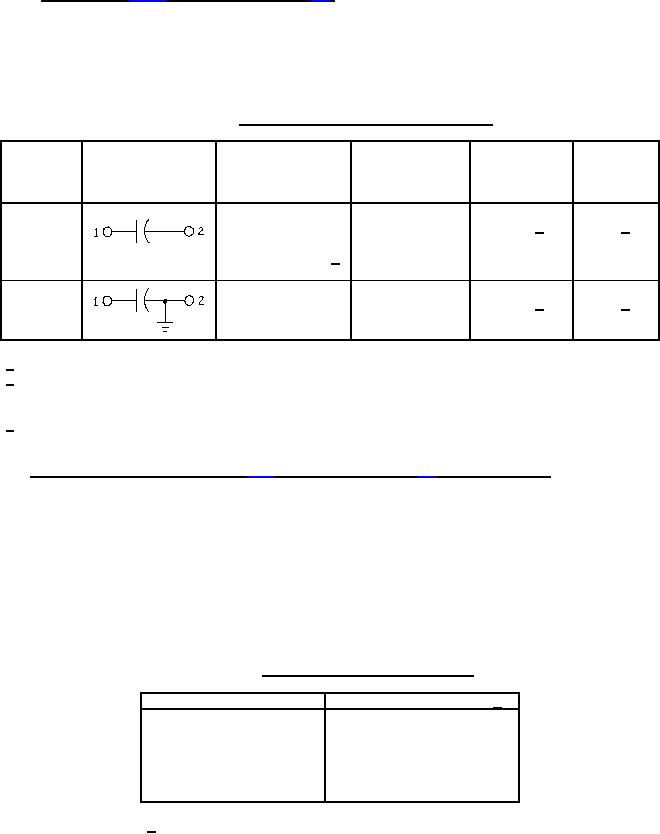
TABLE XV. Dielectric-withstanding-voltage test details.
Duration of
Magnitude of
Circuit-
test voltage application of
diagram
Circuit diagram
Test points
Test connections
voltage
(percent rated
symbol
(minutes)
dc voltage)
200 1/
1 2/
1 to 2
1
Terminal to terminal
1 and 2 to case
Terminal to case 3/
200
1
3
Terminal to terminal 1 to 2 or 1 to case
200 1/
1 2/
1/ 175 percent rated dc voltage after immersion, and moisture resistance tests.
2/ For the 100-percent inspection specified in 4.6.1.2, the capacitors shall be subjected, at the option of the
manufacturer, to the application of 250 percent of rated dc voltage for not less than 5 seconds, or 200
percent for not less than 15 seconds.
3/ For quality conformance inspection, application of potential may be made between each terminal individually
and the case.
4.7.7 Barometric pressure (reduced) (see 3.11) (when applicable. see 3.1), qualification only. Capacitors shall be
tested in accordance with method 105 of MIL-STD-202. The following details and exceptions shall apply:
a. Method of mounting: By normal mounting means.
b. Test condition: Unless otherwise specified (see 3.1), capacitors shall be subjected to a pressure of 0.82
inch of mercury (80,000 feet).
c. Test during subjection to reduced pressure: Unless otherwise specified (see 3.1), a potential equal to that
specified in table XVI, as applicable, shall be applied for at least 1 minute between test points specified
(see 3.1). A suitable means shall be used to detect momentary or permanent breakdown. Capacitors shall
then be visually examined for evidence of damage (see 6.5.5).
TABLE XVI. Barometric-pressure test potentials.
Case diameter (Inch (mm))
DC voltage (max) (Volts) 1/
.175 (4.45)
200
.195 (4.95)
200
.235 (5.97)
300
.312 (7.92)
430
.400 (10.16)
500
.562 (14.27) and up
640
1/ The dc voltage shall be limited to 200 percent of the dc
voltage rating at maximum rated temperature.
21
For Parts Inquires submit RFQ to Parts Hangar, Inc.
© Copyright 2015 Integrated Publishing, Inc.
A Service Disabled Veteran Owned Small Business