MIL-PRF-19978K
1.2.1.1 Style The style is identified by either the three-letter symbol "CQR" or the two-letter symbol "CQ" followed
by a two-digit number. The letters identify plastic (or paper-plastic) dielectric, fixed capacitor, hermetically sealed in
metal, ceramic or glass cases. The symbol "CQR" identifies established reliability (ER) capacitors; the symbol "CQ"
identifies capacitors for which no specific reliability requirements are specified (non-ER). The first digit following the
letter symbols identifies the general shape of the case, and the second digit identifies specific details other than case
size. Each style designation may include a family of case sizes.
1.2.1.2 Terminal. The terminal is identified by a single letter in accordance with table I.
TABLE I. Terminal.
Symbol
Type of terminal
A
Axial wire lead
B
Solder lug (nonremovable)
C
Threaded stud and nuts
D and H
Pillar insulator for use at altitudes up to 7,500 feet (22.8 inches of mercury)
E
Pillar insulator for use at altitudes up to 50,000 feet (3.4 inches of mercury)
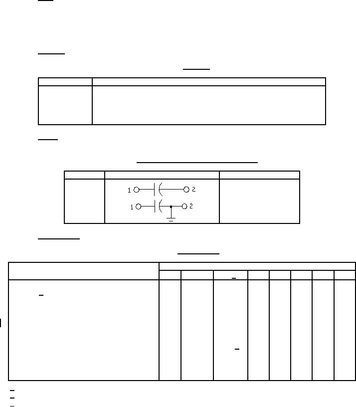
1.2.1.3 Circuit. The circuit diagram and the number of terminals are identified by a single digit in accordance with
table II.
TABLE II. Circuit diagram and number of terminals.
Symbol
Circuit diagram
Number of terminals
1
2
3
2
1.2.1.4 Characteristic. The characteristic is identified by a single letter in accordance with table III.
TABLE III. Characteristic.
Values of characteristics
Characteristic
E
F and G
K 2/
M
P
Q
T
V
High ambient test temperature, degrees Celsius
+85
+85
+125
+85 +65 +125 +170 +125
3C 1/
Low ambient test temperature, degrees Celsius
-65
-55
-65
-65
-65
-55
-65
-55
+0C, -5C
Life-test dc voltage, percent of the dc voltage
rating (see 4.7.20):
Watt-second group (see 6.5.3):
I (0.5 watt-second and less)
140
140
140
140
140
150
140
150
II (0.5+ to 5 watt-seconds)
140
130
140 3/
---
---
---
---
---
III (5+ to 50 watt-seconds)
140
110
140
---
---
---
---
---
IV (greater than 50 watt-seconds)
140
90
140
---
---
---
---
---
Flashpoint of impregnant of filling compound,
+142
+135
+142
+142 +142 +142 +217 +142
degrees Celsius
1/ For characteristic K, voltage derating may be necessary at the high ambient test temperature (see 3.1).
2/ For tubular units of characteristic K rated at 1,000 volts dc, life test voltage is 1,200 volts.
3/ For tubular units of characteristic K in watt-seconds group II, use 130 percent of the dc voltage at +40C for the
life-test dc voltage.
2
For Parts Inquires submit RFQ to Parts Hangar, Inc.
© Copyright 2015 Integrated Publishing, Inc.
A Service Disabled Veteran Owned Small Business