MIL-PRF-19978/1F
SEE TABLE III
SEE TABLE III
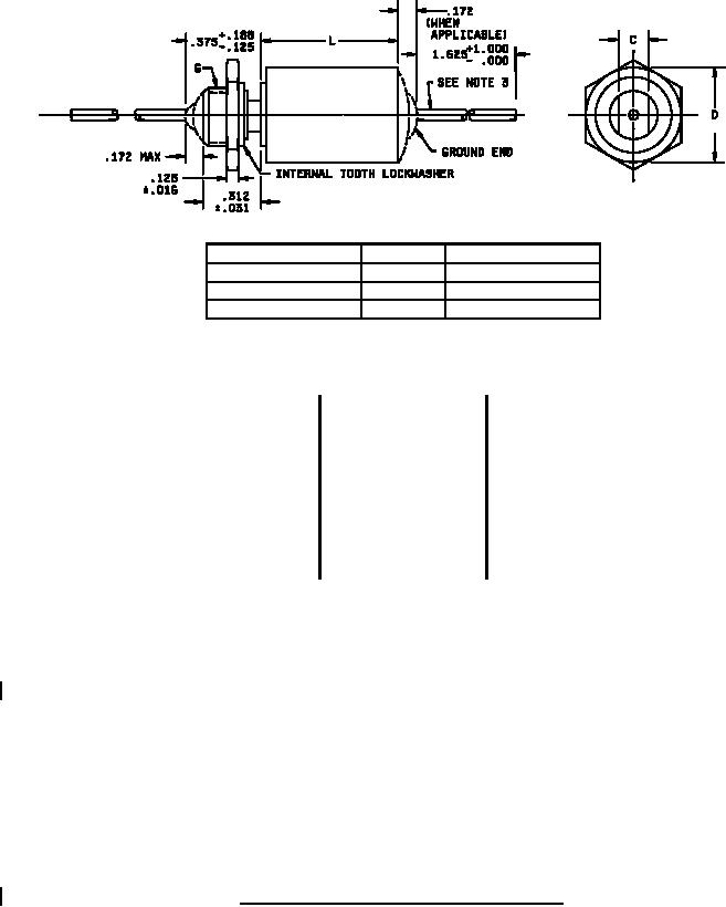
C ±.005
Case dimension D
G
.562 or less
.250
5/16-24 UNF -2A
.670
.375
7/16-28 UNEF -2A
.750 and up
.437
1/2-28 UNEF -2A
Style CQ13 (uninsulated case)
Inches
mm
Inches
mm
Inches
mm
.001
0.03
.144
3.66
.437
11.10
.004
0.10
.156
3.96
.438
11.13
.005
0.13
.172
4.37
.500
12.70
.016
0.41
.175
4.45
.562
14.27
.020
0.51
.188
4.78
.670
17.02
.025
0.64
.195
4.95
.750
19.05
.031
0.79
.235
5.97
1.000
25.40
.032
0.81
.250
6.35
1.562
39.67
.062
1.57
.312
7.92
1.625
41.28
.0625
1.59
.375
9.53
.125
3.18
.400
10.16
NOTES
1. Dimensions are in inches.
2. Metric equivalents are given for general information only.
3. Basic case dimensions for the insulated styles shall be the same as for the uninsulated styles.
4. Leads shall be of solder coated solid wire, .020 (No. 24 AWG) for cases .175 and .195 in diameter; .025 (No. 22
AWG) for cases .235 through .312 diameter; and .032 (No. 20 AWG) for cases .400 diameter and above except
that style CQ13 capacitors shall be furnished with .032 (No. 20 AWG) lead wire. Tolerance on all lead wire
diameters shall be +.004, -.001.
5. Capacitors with dimension L of 1.562 or D of .562 and larger, are not intended to be supported by their leads.
These capacitors shall be supported with a supplementary means of mounting such as tangential retainer for
style CQ08, and a wrap-around hand for style CQ09. The supporting device will not be supplied with the
capacitor. Style CQ13 shall be supplied with mounting nuts and lockwashers.
6. Lead length may be a minimum of 1-inch long for use in tape and reel packaging when specified in the ordering
data.
FIGURE 1. Styles CQ08, CQ09, CQ12 and CQ13 capacitors - Continued.
2
For Parts Inquires submit RFQ to Parts Hangar, Inc.
© Copyright 2015 Integrated Publishing, Inc.
A Service Disabled Veteran Owned Small Business