INCH-POUND
MIL-C-19978/16B
18 June 2001
SUPERSEDING
MIL-C-19978/16A
30 September 1982
MILITARY SPECIFICATION SHEET
CAPACITORS, FIXED, PLASTIC (OR PAPER-PLASTIC) DIELECTRIC,
AXIAL-WIRE TERMINAL, TUBULAR (INSULATED),
(HERMETICALLY SEALED IN METAL CASES),
ESTABLISHED RELIABILITY, STYLE CQR39
INACTIVE FOR NEW DESIGN
AFTER 20 OCTOBER 1972
This specification is approved for use by all Departments
and Agencies of the Department of Defense.
The requirements for acquiring the product described herein
shall consist of this specification and MIL-PRF-19978.
Inches
mm
Inches
mm
.001
0.03
.312
7.92
.004
0.10
.400
10.16
.025
0.64
.562
14.27
.032
0.81
1.000
25.40
.172
4.37
1.562
39.67
NOTES:
.235
5.97
1.625
41.38
1.
Dimensions are in inches.
2.
Metric equivalents are given for general information only.
3.
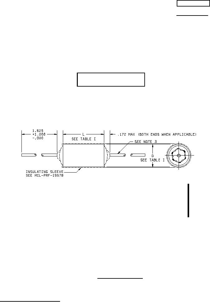
Leads shall be of tinned solid wire, .025 (No. 22 AWG) for cases .235 and .312 in diameter; and .032
(No. 20 AWG) for cases .400 diameter and above. Tolerance on all lead wire diameters shall be + .004,
-.001.
4.
Capacitors with dimension L of 1.562 or D of .562 and larger, are not intended to be supported by their
leads. These capacitors shall be supported with a supplementary means of mounting, such as a wrap-
around band. The supporting device will not be supplied with the capacitor.
5.
Lead length may be a minimum of 1.00 inch long for use in tape and reel packaging when specified in
the ordering data.
FIGURE 1. Style CQR39 capacitors.
AMSC N/A
1 of 8
FSC 5910
DISTRIBUTION STATEMENT A. Approved for public release; distribution is unlimited.