MIL-PRF-87217A
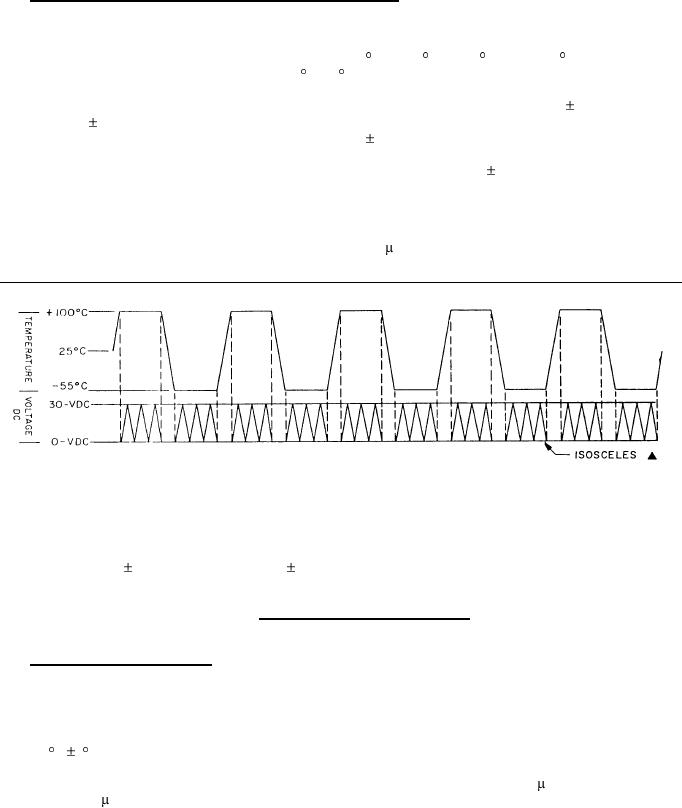
4.7.4 High impedance temperature and voltage ramp (see figure 1).
a. Each part shall be connected with 1-10 megohms in series.
b. Parts shall be temperature ramped for 5 cycles from 25 C to 100 C, to -55 C, and to 25 C with an equally
timed stay at the temperature extremes (100 C/-55 C).
c. Parts shall be voltage ramped during the temperature extremes only. A 0 volt to 30 volt ( 10%) ramp in 30
minutes ( 3 minutes) shall be applied to the RC circuit. After the capacitor reaches 30 volts charge, the
capacitors will be linearly discharged within 30 minutes 3 minutes. When the voltage reaches 200
millivolts, the voltage ramp to 30 volts is repeated (3 ramps during each exposure at the temperature
extremes). For capacitance values above 10 microfarads, use a 60 minute 6 minute ramp to 30 volts.
d. Parts shall be monitored for high leakage current continuously, or scanned at a minimum of once every 0.5
seconds, during the 5 temperature cycles. Noise shall be limited to 6 mV, peak.
e. A permanent record of current excursions in excess of .05 A shall be maintained.
STABILIZE CAPACITORS AT TEMPERATURE EXTREMES AND VOLTAGE RAMP 3 TIMES
(0 TO 30 V dc) 10% AND (30 TO 0 V dc) 10% WHILE MONITORING FOR LEAKAGE CURRENT
FIGURE 1. Voltage and temperature ramp test.
4.7.5 Insulation resistance (see 3.9). Capacitors shall be tested in accordance with method 302 of MIL-STD-202.
The following details shall apply:
a. Test potential: Rated voltage, unless otherwise specified (see 3.1).
b. Points of measurement: Between terminals at the applicable specified temperatures (see 3.1), and at
25 C 3 C.
c. Charge time 5 minutes maximum; however, for capacitance values greater than 1.0 F, an additional 1
minute per F is permitted.
8
For Parts Inquires submit RFQ to Parts Hangar, Inc.
© Copyright 2015 Integrated Publishing, Inc.
A Service Disabled Veteran Owned Small Business