MIL-PRF-83421E
4.7.3 Dielectric absorption (when specified, see 3.1 and 3.7). The capacitor shall be charged at dc rated voltage
or 100 volts dc (whichever is less) for a minimum period of 5 minutes. The initial surge current shall not exceed 50
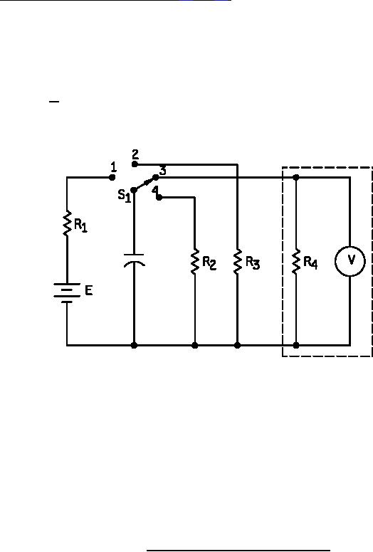
milliamperes. A typical test schematic is shown in figure 1. At the end of this period, the capacitor shall be
disconnected from the power source and discharged through a 5 ohm ±1 percent resistor for 5 ±0.5 seconds. The
discharge resistor shall be disconnected from the capacitor at the end of the 5 second discharge period; and after 1
minute, the voltage remaining on the capacitor (recovery voltage) shall be measured with an electrometer, or other
suitable device having an input resistance of 10,000 megohms, or greater. The dielectric absorption shall be
d
computed from the following formula:
V
V
Where:
=
Dielectric absorption (percent).
=
Maximum recovery voltage.
=
Charging voltage.
E = DC rated voltage or 100 volts dc, whichever is less (±2 percent)
R1 and R2 = 1000 ohms ±20 percent (this value not critical).
R3 = 5 ohms ±1 percent.
R4 = 10,000 megohms, minimum.
Suggest use of ±1230A GR electrometer or equivalent with 10,000 megohms, minimum, input resistance.
NOTES:
1. Charge for 5 minutes ±10 seconds with switch in position 1.
2. Switch in position 2 for 5 seconds ±0.5 seconds.
3. Switch in position 3.
4. After 1 minute read recovery voltage and compute as a percentage of charge voltage.
5. Switch to position 4, discharge and remove.
FIGURE 1. Typical dielectric absorption test schematic.
17
For Parts Inquires submit RFQ to Parts Hangar, Inc.
© Copyright 2015 Integrated Publishing, Inc.
A Service Disabled Veteran Owned Small Business