MIL-PRF-83421/2D
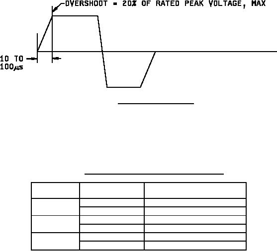
FIGURE 2. Waveform characteristics.
Insulation resistance (IR): Method 302 of MIL-STD-202. Charge to rated voltage, +105°C for 5 minutes
maximum; however, for capacitance values greater than 1.0 µF, an additional 1 minute per µF is permitted.
Terminal to terminal: See table II.
TABLE II. Insulation resistance versus capacitance value.
Minimum insulation resistance
Temperature
Capacitance
(terminal to terminal)
0µF to .1µF
3,000,000 megohms
+25°C
Greater than .1µF
300,000 megohm-microfarads
0µF to .1µF
150,000 megohms
+85°C
Greater than .1µF
15,000 megohm-microfarads
0µF to .1µF
20,000 megohms
+105°C
Greater than .1µF
2,000 megohm-microfarads
Dissipation factor (DF): 0.07 percent maximum.
Barometric pressure (reduced): Method 105 of MIL-STD-202, condition D (100,000 feet). 125 percent of dc rated
voltage applied. See MIL-PRF-83421 for voltage limitations.
Vibration, random (optional): In accordance with MIL-PRF-83421 when ordered with "-" replaced with "H" in the
PIN.
AC burn-in: 40 kHz for 24 hours ± 8 hours at rms current as specified in table I at +85°C.
Dielectric absorption: 0.1 percent maximum.
Immersion: Method 104 of MIL-STD-202, test condition C.
DWV:
Insulating sleeves: Greater than 4,000 volts, dc.
Terminal to terminal: 200 percent of dc rated voltage.
Terminals to case: 200 percent of dc rated voltage.
5
For Parts Inquires submit RFQ to Parts Hangar, Inc.
© Copyright 2015 Integrated Publishing, Inc.
A Service Disabled Veteran Owned Small Business