MIL-PRF-83421/1D
REQUIREMENTS:
Case material: Nonmagnetic (end seals may be of magnetic material).
Leads:
.500 inch (12.70 mm) and smaller case diameters: Composition W and final finish 32 of MIL-STD-1276.
Composition N and final finish 32 of MIL-STD-1276 may be furnished when specified in contract or order
(see MIL-PRF-83421 ordering data).
.562 inch (14.27 mm) and larger case diameters: Composition C and final finish 32 of MIL-STD-1276.
Capacitance value: See table I.
Capacitance tolerance: See table I.
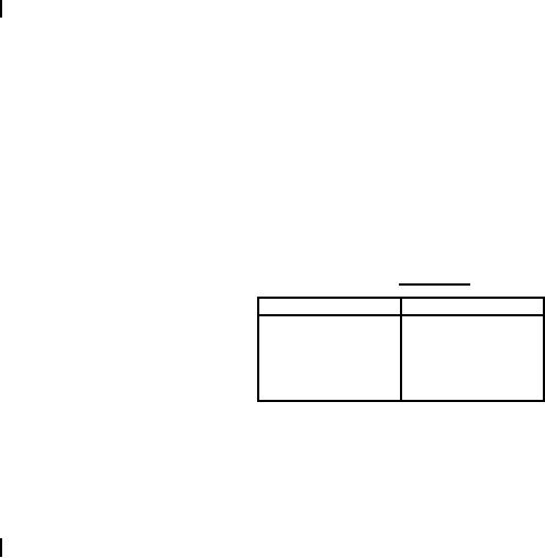
TABLE II. DC ratings.
Styles
Volts, dc
30
CRH01, CRH06
50
CRH02, CRH07
100
CRH03, CRH08
200
CRH04, CRH09
400
CRH05, CRH00
Operating temperature range: -65C to +100C; derate linearly from +100C to 50 percent of rated voltage at
+125C.
Failure rate (FR) level: M (1.0%), P (0.1%), R (0.01%), and S (0.001%) (established at dc rated voltage at
+100C ).
Burn-in (styles CRH01 through CRH05 only): 140 percent minimum of dc rated voltage shall be applied for 48
hours minimum at +125C +4C, -0C.
Thermal shock: Method 107 of MIL-STD-202, test condition B.
Styles CRH01 through CRH05: 10 cycles.
Styles CRH06 through CRH00: 5 cycles.
Seal: Method 112 of MIL-STD-202, test condition C, procedure IIIa with the following exceptions and details: A
bomb pressure of 45 5 lbf/in (gage), exposure time of 1 hour +1 hour, -0 hour, and dwell time of 1 hour
2
-6
3
-5
maximum. The reject limit for styles CRH01 through CRH05 is R1 = 1 X 10 atm cm /s and R1 = 1 X 10 atm
3
cm /s for styles CRH06 through CRH00. Upon completion of test condition C, perform either test condition A,
test condition B with mineral oil, or test condition D.
10
For Parts Inquires submit RFQ to Parts Hangar, Inc.
© Copyright 2015 Integrated Publishing, Inc.
A Service Disabled Veteran Owned Small Business