MIL-PRF-81/1E
REQUIREMENTS:
Dimensions and configuration: See figure 1.
Capacitance value: See table I.
DC rated voltage: See table I.
Operating temperature range: -55°C to +85°C.
Characteristics: See table I.
Dielectric withstanding voltage:
Method 301 of MIL-STD-202:
A dc potential of 2.2 times rated voltage applied between terminals for 3 seconds ±2 seconds.
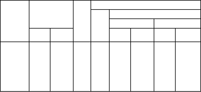
TABLE I. Style CV11.
Characteristics
Type
Capacitance
DC
designation
(pF)
rated
Symbol
Capacitance change from value at 25°C
voltage
(volts)
At -55°C
At +85°C
Minimum
Maximum
Minimum
Maximum
Minimum
Maximum
percent
percent
percent
percent
CV11A070
1.5
7.0
500
A
-4.5
+2.0
-2.5
+2.0
CV11A120
3.0
12.0
500
A
-4.5
+2.0
-2.5
+2.0
CV11A250
4.5
25.0
500
A
-4.5
+2.0
-2.5
+2.0
CV11B130
3.0
13.0
500
B
-1.0
+3.5
-2.5
-0.5
CV11B200
5.0
20.0
500
B
-1.0
+3.5
-2.5
-0.5
CV11C300
4.0
30.0
500
C
-1.0
+6.5
-4.0
-1.0
CV11C450
7.0
45.0
500
C
-1.0
+6.5
-4.0
-1.0
CV11D060
2.0
6.0
500
D
+1.5
+8.2
-5.0
-1.5
CV11D300
4.0
30.0
500
D
+1.5
+8.2
-5.0
-1.5
CV11D450
7.0
45.0
500
D
+1.5
+8.2
-5.0
-1.5
Barometric pressure:
Method 105 of MIL-STD-202, condition D (100,000 feet) and condition B (50,000 feet).
Test potential: 80 percent of dc rated voltage for condition D and 125 percent dc rated voltage for
condition B.
Insulation resistance:
Method 302 of MIL-STD-202, condition A, 100 volts dc applied: 10,000 megohms, minimum.
Capacitance:
Method 305 of MIL-STD-202.
DF: At 1 MHz ±100 kHz, at maximum and minimum capacitance: Shall be not more than 0.2 percent.
2