INCH-POUND
MIL-PRF-55681/6A
3 July 1997
SUPERSEDING
MIL-C-55681/6
30 July 1981
PERFORMANCE SPECIFICATION SHEET
CAPACITOR, CHIP, MULTIPLE LAYER, FIXED, CERAMIC DIELECTRIC,
ESTABLISHED RELIABILITY AND NON-ESTABLISHED RELIABILITY,
STYLES CDR26, CDR27, CDR28, CDR29, AND CDR30
This specification is approved for use by all Departments
and Agencies of the Department of Defense.
The requirements for acquiring the product described herein
shall consist of this specification sheet and MIL-PRF-55681.
Inches
mm
.010
0.25
.030
0.76
.040
1.02
Dimensions
Style
L
W
EB
min
max
.150 (3.81) +..015 (0.38)
.150 (3.81) +.015 (0.38)
.030
CDR26
.010
.190 (4.83) +. .019 (0.48)
.190 (4.83) +. .019 (0.48)
.030
CDR27
.010
.330 (8.38) +. .033 (0.84)
.330 (8.38) +. .033 (0.84)
.040
CDR28
.010
.040
CDR29
.010
.400 (10.16) +. .040 (1.02)
.400 (10.16) + .040 (1.02)
.040
CDR30
.010
.540 (13.72) +. .054 (1.37)
.400 (10.16) + .040 (1.02)
NOTES:
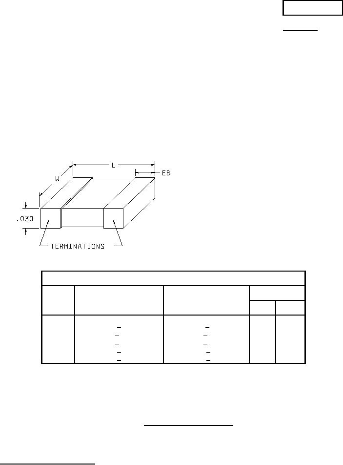
1. Dimensions are in inches.
2. Metric equivalents are given for information only.
3. Dimensions and tolerances are for bare chip. For solder coated terminations, add .020 (0.51 mm) to the length
and .012 (0.30 mm) to the width and thickness.
FIGURE 1. Dimensions and configuration.
AMSC N/A
1 of 7
FSC 5910
DISTRIBUTION STATEMENT A. Approved for public release; distribution is unlimited.