MIL-PRF-55514/1C
*
TABLE I. Style CFR02 capacitor characteristics - Continued.
CHARACTERISTICS Q AND V CAPACITORS
Type designation Capacitance Rated voltage Capacitance
Dimensions (in inches)
(nom) µF
(at 85°C)
1/
tolerance
L ±.062 (1.57) M +.005 (.13) 3/
D 2/
available
volts, dc
M -.003 (.08) 3/
.032 (.81)
1.594 (40.49)
.797 (20.24)
F, G, J, K
200
.56
CFR02A-C564--
.032 (.81)
1.594 (40.49)
.859 (21.82)
F, G, J, K
200
.68
CFR02A-C684--
.032 (.81)
1.844 (46.84)
.859 (21.82)
F, G, J, K
200
.82
CFR02A-C824--
.032 (.81)
1.844 (46.84)
.938 (23.83)
F, G, J, K
200
1.00
CFR02A-C105--
*
The complete type designation will include additional symbols to indicate characteristic (V or Q), capacitance
1/
tolerance and product level (C, M, P, R, or S).
Tolerances for dimension "D" are ±.031 (.250 inch diameter and below); ±.046 (.251 through .499 inch diameter);
2/
and ±.062 (.500 inch diameter and above).
Comparable AWG sizes are No. 22 (.025 inch) and No. 20 (.032 inch).
3/
*
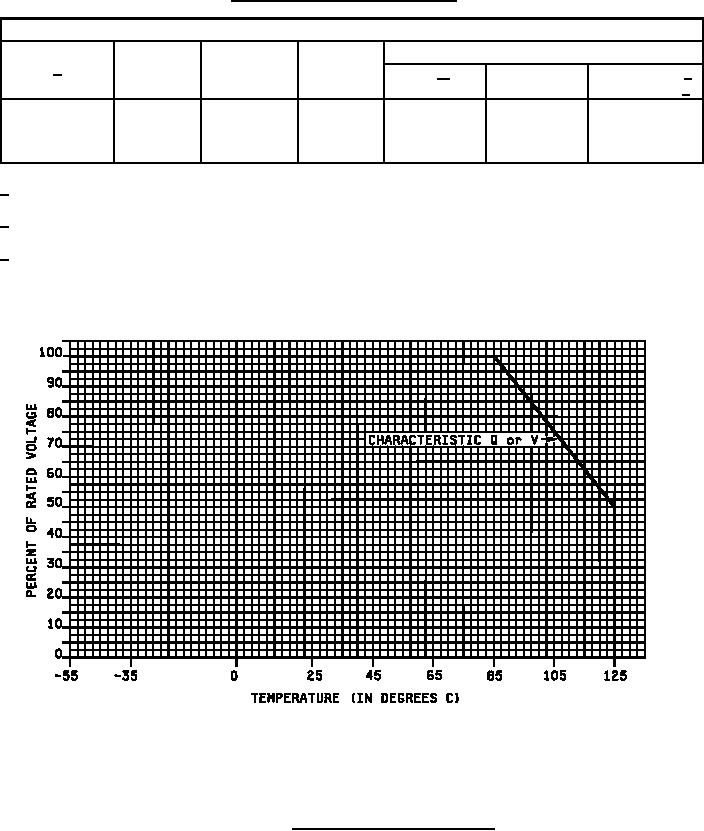
FIGURE 2. Voltage derating with temperature.
6