MIL-PRF-39022/1G
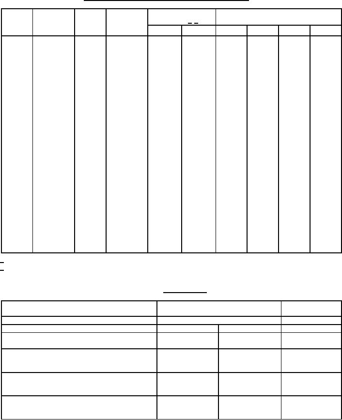
TABLE I. Electrical characteristics, dimensions, and dash numbers - Continued.
Dimension, nominal
Dash number
DC rated
Capacitance
Capacitance
Circuit
(inches) 1/ 2/
Failure rate level (%/1,000 hr)
voltage
tolerance
value
diagram
(Percent ±)
(µF)
(Volts)
L ± 0.062
D ± 0.031
M(1.0)
P(0.1)
R(0.01)
S(0.001)
10
2261
1481
1
2001
.400
0.047
1741
1.125
600
20
2262
1482
1
2002
.400
0.047
1742
1.125
600
10
2263
1483
3
2003
.400
0.047
1743
1.062
600
20
2264
3
2004
.400
0.047
1744
1.062
600
1484
2265
1
2005
.500
0.10
1745
1.125
600
1485
10
2266
1
2006
.500
0.10
1746
1.125
600
1486
20
2267
3
2007
.500
0.10
1747
1.062
600
1487
10
3
2008
.500
0.10
1748
1.062
600
1488
20
2268
1
2029
.562
0.15
1769
1.125
600
1509
10
2289
1
2030
.562
0.15
1770
1.125
600
1510
20
2290
3
2031
.562
0.15
1771
1.062
600
1511
10
2291
3
2032
.562
0.15
1772
1.062
600
1512
20
2292
1
2009
.562
0.22
1749
1.375
600
1489
10
2269
1
2010
.562
0.22
1750
1.375
600
1490
20
2270
3
2011
.562
0.22
1751
1.312
600
1491
10
2271
3
2012
.562
0.22
1752
1.312
600
1492
20
2272
1
2013
.670
0.47
1753
1.625
600
1493
10
2273
1
2014
.670
0.47
1754
1.625
600
1494
20
2274
3
2015
.670
0.47
1755
1.562
600
1495
10
2275
3
2016
.670
0.47
1756
1.562
600
1496
20
2276
1
2017
1.000
1.0
1757
1.844
600
1497
10
2277
1
2018
1.000
1.0
1758
1.844
600
1498
20
2278
3
2019
1.000
1.0
1759
1.781
600
1499
10
2279
3
2020
1.000
1.0
1760
1.781
600
1500
20
2280
1
2021
1.000
1.5
1761
1.875
600
1501
10
2281
1
2022
1.000
1.5
1762
1.875
600
1502
20
2282
3
2023
1.000
1.5
1763
1.812
600
1503
10
2283
3
2024
1.000
1.5
1764
1.812
600
1504
20
2284
1
2025
1.000
2.2
1765
2.625
600
1505
10
2285
1
2026
1.000
2.2
1766
2.625
600
1506
20
2286
3
2027
1.000
2.2
1767
2.562
600
1507
10
2287
3
2028
1.000
2.2
1768
2.562
600
1508
20
2288
1/ Dimensions shown are bare case sizes (see figure 1).
2/ Metric equivalents, see table III.
TABLE II. Characteristics.
Polyethylene-
Dielectric material
Paper-polyethylene-terephthalate
terephthalate
-55°C to +125°C
-55°C to +85°C
Operating temperature range
DC voltage rating (volts)
200 V
400 V, 600 V
50 V
+125°C +4°C, -0°C +125°C +4°C, -0°C
+85°C +4°C, -0°C
High ambient test temperature
-55°C +0°C, -3°C
-55°C +0°C, -3°C
-55°C +0°C, -3°C
Low ambient test temperature
Megohms x microfarads (minimum)
At +25°C
2,000
2,000
25,000
10
40
3,000
At high ambient test temperature
Insulation resistance (megohms) (need not exceed)
At +25°C
12,000
12,000
50,000
150
600
6,000
At high ambient test temperature
Capacitance change with temperature (maximum)
At -55°C
-10
-10
-8 percent
+20
+20
+8 percent
At high ambient test temperature
7
For Parts Inquires submit RFQ to Parts Hangar, Inc.
© Copyright 2015 Integrated Publishing, Inc.
A Service Disabled Veteran Owned Small Business