MIL-PRF-20/37F
REQUIREMENTS:
Dimensions and configuration: See figure 1.
Lead type: Radial.
Case type: Molded.
DC rated voltage: See table I.
Operating temperature range: -55°C to +125°C.
Characteristic: CG.
Failure rate level (CCR07 only): M (1.0 percent), P (0.1 percent), R (.01 percent) or S (.001 percent).
Thermal shock and voltage conditioning (CCR07 only): In accordance with MIL-PRF-20.
Capacitance: Within tolerance specified (see table I).
Dissipation factor: In accordance with MIL-PRF-20.
Dielectric withstanding voltage: In accordance with MIL-PRF-20.
Body insulation: Test II.
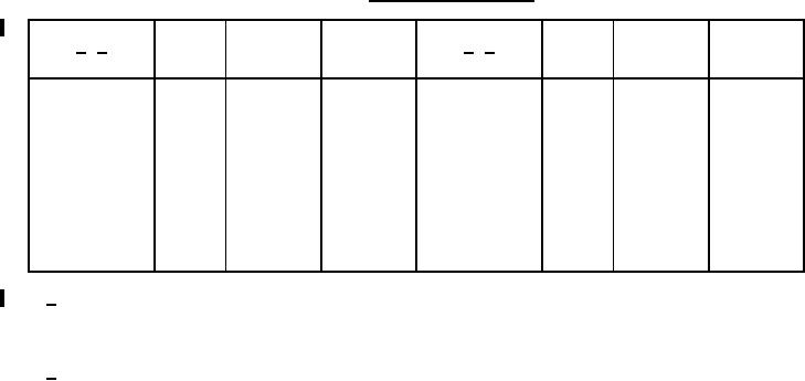
TABLE I. Capacitor characteristics.
PIN
PIN
Capacitance
Capacitance
Rated
Rated
Nominal
Nominal
1/ 2/
1/ 2/
tolerance
tolerance
voltage capacitance
voltage capacitance
(pF)
(pF)
(volts, dc)
(volts, dc)
FGJK
18,000
50
CC-07CG183--
FGJK
2,200
200
CC-07CG222--
FGJK
22,000
50
CC-07CG223--
FGJK
2,700
200
CC-07CG272--
27,000
50
CC-07CG273--
FGJK
3,300
200
CC-07CG332--
FGJK
33,000
50
CC-07CG333--
FGJK
3,900
200
CC-07CG392--
FGJK
39,000
50
CC-07CG393--
FGJK
4,700
200
CC-07CG472--
FGJK
47,000
50
CC-07CG473--
FGJK
5,600
100
CC-07CG562--
FGJK
56,000
50
CC-07CG563--
FGJK
6,800
100
CC-07CG682--
FGJK
68,000
50
CC-07CG683--
FGJK
8,200
100
CC-07CG822--
FGJK
82,000
50
CC-07CG823--
FGJK
10,000
100
CC-07CG103--
FGJK
100,000
50
CC-07CG104--
FGJK
12,000
100
CC-07CG123--
FGJK
FGJK
15,000
50
CC-07CG153--
1/ Complete PIN will include the following:
1st dash - Symbol "R" (for style CCR07) or dash will be deleted (for style CC07).
2nd dash - Applicable capacitance tolerance symbol.
3rd dash - Applicable failure rate level symbol (CCR07 only) or dash will be deleted (for style CC07).
2/ Capacitors deleted since previous revisions shall be replaced by selecting a capacitor with the nearest
parameter.
2
For Parts Inquires submit RFQ to Parts Hangar, Inc.
© Copyright 2015 Integrated Publishing, Inc.
A Service Disabled Veteran Owned Small Business