MIL-PRF-20/36G
Dielectric withstanding voltage: In accordance with MIL-PRF-20.
Body insulation: Test II.
Solderability: The leads shall be solderable up to .020 inch (0.51 mm) from the body egress.
Resistance to soldering heat: In accordance with MIL-PRF-20.
Workmanship: For style CCR06 with standoff, exposed copper or bare leads shall be permitted to a maximum of
.020 inch (0.51 mm) from the body egress. For style CCR06 without standoffs and style CC06, workmanship
shall be in accordance with MIL-PRF-20.
Life: In accordance with MIL-PRF-20, operating condition 2.
Part or Identifying Number (PIN): In accordance with MIL-PRF-20 and table I.
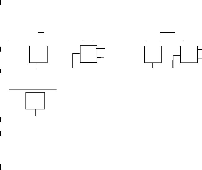
Marking: Method I of MIL-STD-1285. At the option of the manufacturer, the marking may be placed on one side
of the capacitor, or the marking may be placed on two lines as long as it is in the same order as shown in the
following examples:
ER
NON-ER
BACK
FRONT
BACK
FRONT WITHOUT STANDOFFS
DATE &
DATE & LOT CODE
LOT CODE
1120A
CC06
CCR06
1120A
J200V
CG
CG242
CG
CAGE
CAGE
12345
242F
12345
FM
PIN
"J" BRAND
PIN
LOT CODE
& VOLTAGE
FRONT WITH STANDOFFS
CCR06
CG242
FMV
PIN
Referenced documents. In addition to MIL-PRF-20, this specification sheet references the following document:
Changes from previous issue: The margins of this specification sheet are marked with vertical lines to indicate
where changes from the previous issue were made. This was done as a convenience only and the Government
assumes no liability whatsoever for any inaccuracies in these notations. Bidders and contractors are cautioned to
evaluate the requirements of this document based on the entire content irrespective of the marginal notations and
relationship to the last previous issue.
4
For Parts Inquires submit RFQ to Parts Hangar, Inc.
© Copyright 2015 Integrated Publishing, Inc.
A Service Disabled Veteran Owned Small Business