MIL-PRF-20/36G
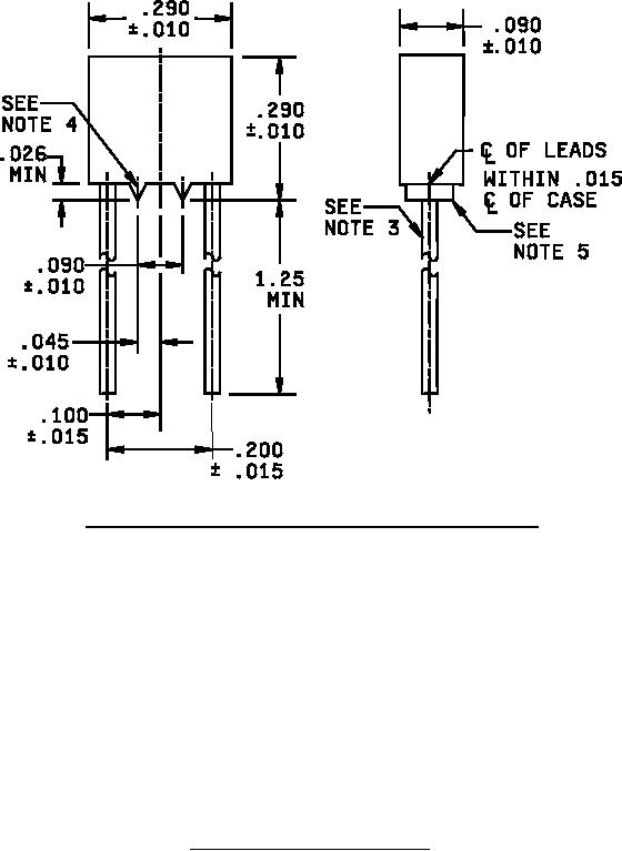
OPTIONAL CONFIGURATION WITH STANDOFFS (CCR06 ONLY)
NOTES:
Inches
mm
1. Dimensions are in inches.
.010
0.25
2. Metric equivalents are given for information only.
.015
0.38
3. Lead diameter shall be .023 (0.58 mm) to .029 (0.74 mm).
.026
0.66
4. Optional standoffs for style CCR06 shall be of triangular shape so that the
.045
1.14
standoffs will provide line contact with surface upon which the capacitor is
.090
2.29
mounted. The shape of the triangle is optional.
.100
2.54
5. Thickness of standoffs shall be .075 (1.90 mm) to the body thickness.
.200
5.08
6. Lead length may be a minimum of .625 (15.88 mm) for use in tape and reel
.290
7.37
automatic insertion equipment, when specified.
1.250
31.80
7. At the option of the user, the standoff configuration may be furnished as a
replacement for the nonstandoff configuration of the same style.
FIGURE 1. Styles CCR06 and CC06 capacitors - Continued.
2
For Parts Inquires submit RFQ to Parts Hangar, Inc.
© Copyright 2015 Integrated Publishing, Inc.
A Service Disabled Veteran Owned Small Business