MIL-PRF-19978/5B
REQUIREMENTS:
Design and construction:
Dimensions and configuration - See figure 1 and table II.
Case material - Nonmagnetic.
Terminals - Axial-wire lead (see figure 1).
3
Rated voltage - See table II.
Rated temperature - -65 to +125 C.
Capacitance (cap.) (nom) - See table II.
Capacitance tolerance - See table II.
Dissipation factor (DF) (max) - 0.15 percent.
Seal: Method 112 of MIL-STD-202, test condition letter A.
Dielectric withstanding voltage (DWV):
Sleeving - In accordance with MIL-PRF-19978.
Barometric pressure: In accordance with MIL-PRF-19978.
Test points:
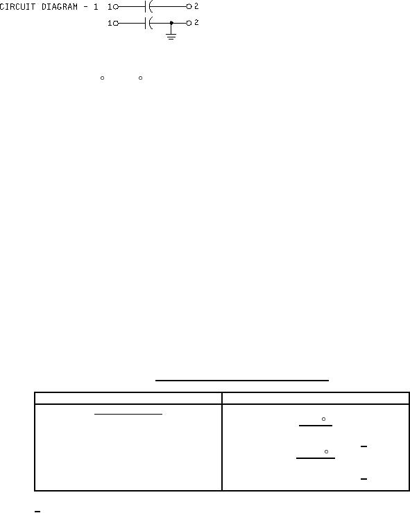
Circuit diagram 1 - Between terminals and case.
Circuit diagram 3 - Between ungrounded terminal and case.
Insulation resistance (IR):
Sleeving - In accordance with MIL-PRF-19978.
Terminal to terminal - See table I.
TABLE I. Terminal-to-terminal insulation resistance.
Capacitance rating
Minimum insulation resistance
Characteristic Q
At 25 C
0 to 0.5 microfarad
100,000 megohms
Greater than 0.5 microfarad
50,000 megohm-microfarads 1/
At 125 C
0 to 0.1 microfarad
5,000 megohms
Greater than 0.1 microfarad
500 megohm-microfarads 1/
1/
Product obtained by multiplying the capacitance in microfarads by the insulation
resistance in megohms.
2