MIL-C-18312G
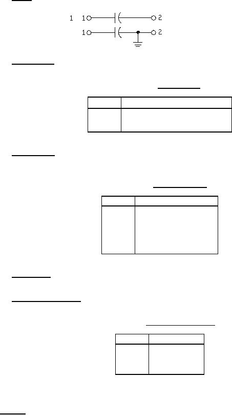
1.2.1.3 Circuit. The circuit diagram (and the number of terminals associated with each diagram) is identified by a
single number as shown:
3
1.2.1.4 Characteristic. The characteristic is identified by a single letter as shown in table II.
TABLE II. Characteristic.
Symbol
Operating temperature range
-55 to +85°C
R
-55 to +125°C
N
1.2.1.5 Voltage rating. The dc voltage rating is identified by a single letter as shown in table III. For recommended
ac ratings, see 6.9.
TABLE III. DC voltage rating.
Symbol
DC voltage rating (volts)
A
50
V
150
C
200
E
400
F
600
1.2.1.6 Capacitance. The nominal capacitance value expressed in picofarads (pF) is identified by a three-digit
number; the first two digits represent significant figures and the last digit specifies the number of zeros to follow.
1.2.1.7 Capacitance tolerance. The capacitance tolerance is identified by a single letter as shown in table IV.
TABLE IV. Capacitance tolerance.
Symbol
Tolerance
±5
J
±10
K
±20
M
2. APPLICABLE DOCUMENTS
2.1 General. The documents listed in this section are specified in sections 3 and 4 of this specification. This
section does not include documents cited in other sections of this specification or recommended for additional
information or as examples. While every effort has been made to ensure the completeness of this list, document
users are cautioned that they must meet all specified requirements documents cited in sections 3 and 4 of this
specification, whether or not they are listed.
2
For Parts Inquires submit RFQ to Parts Hangar, Inc.
© Copyright 2015 Integrated Publishing, Inc.
A Service Disabled Veteran Owned Small Business