MIL-C-11015/24F
Dimensions
Style
+.025 (.64)
+.006 (.15)
H (Ref)
W
.020 (.51)
L .020 (.51)
C .020 (.51)
T
M
-.050 (1.27)
-.001 (.03)
CK50
.080 (2.03)
.080 (2.03)
.075 (1.91)
.100 (2.54)
.016 (.41)
.170 (4.32)
CK51
.130 (3.30)
.130 (3.30)
.075 (1.91)
.100 (2.54)
.016 (.41)
.200 (5.08)
CK52
.180 (4.57)
.180 (4.57)
.100 (2.54)
.100 (2.54)
.020 (.51)
.250 (6.35)
CK53
.280 (7.11)
.280 (7.11)
.125 (3.18)
.200 (5.08)
.020 (.51)
.350 (8.89)
CK54
.380 (9.65)
.380 (9.65)
.125 (3.18)
.200 (5.08)
.020 (.51)
.450 (11.43)
CK55
.480 (12.19)
.480 (12.19)
.175 (4.45)
.400 (10.16)
.025 (.64)
.550 (13.97)
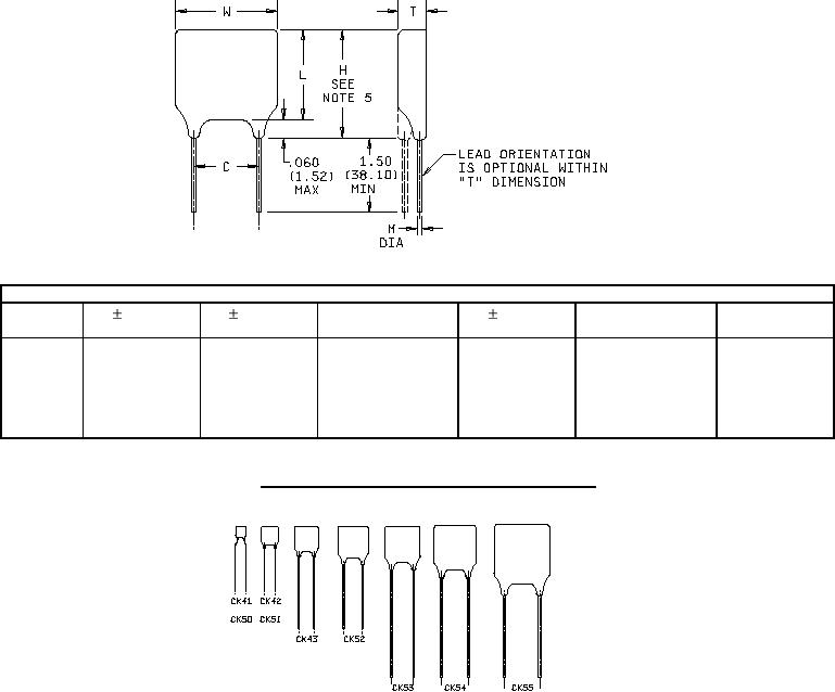
FIGURE 2. Styles CK50, CK51, CK52, CK53, CK54, and CK55.
ACTUAL SIZE (APPROXIMATE)
NOTES:
1. Dimensions are in inches.
2. Metric equivalents are in parentheses.
3. Metric equivalents are given for general information only.
4. Lead length shall be .750 (19.05 mm) to 1.50 (38.10 mm) for styles CK41 and CK42 and 1.25 (31.75 mm) to
1.50 (38.10 mm) for style CK43.
5. H dimension is for reference purposes to indicate the maximum overall mounting height of the capacitor.
Leads shall be solderable beyond this point.
2
For Parts Inquires submit RFQ to Parts Hangar, Inc.
© Copyright 2015 Integrated Publishing, Inc.
A Service Disabled Veteran Owned Small Business