MIL-PRF-81/8A
REQUIREMENTS:
Dimensions and configuration: See figure 1.
Capacitance value: See table I.
DC rated voltage: 100 V dc.
Operating temperature range: -55°C to +85°C.
Characteristics: See table I.
Dielectric withstanding voltage: Method 301 of MIL-STD-202. A dc potential of 2.2 times rated voltage applied
between terminals for 3 seconds ±2 seconds.
Barometric pressure (reduced): Method 105 of MIL-STD-202, condition D (100,000 feet).
Test potential: 100 percent of dc rated voltage.
Insulation resistance: Method 302 of MIL-STD-202, condition A, 100 volts dc applied: 10,000 megohms,
minimum.
Capacitance:
Method 305 of MIL-STD-202.
DF: At 1 MHz ±100 kHz, at maximum and minimum capacitance: Shall be not more than 0.2 percent for rated
maximum capacitance 11 pF, 20 pF, and 30 pF, 0.3 percent for 7 pF.
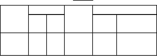
TABLE I. Style CV42.
Type
Capacitance
DC
Characteristic
rated
designation
voltage
Symbol
Temperature
Min.
Max.
(volts)
coefficient
(pF)
(pF)
(ppm/°C)
0 ±200
X
100
7.0
2.0
CV42X070
-450 ±300
Y
100
11.0
3.0
CV42Y110
-750 ±300
Z
100
20.0
4.2
CV42Z200
-750 ±300
Z
100
30.0
5.2
CV42Z300
Temperature coefficient: Within the limits specified for the applicable characteristic.
Capacitance drift: Within 0.50 picofarad (pF) of initial step 1 measurement.
Terminal strength:
Pull test: Capacitor held by body and 4-pound load applied to each terminal for at least 10 seconds.
Torque: Not less than 0.3 ounce-inch nor more than 2 ounce-inches.
Shock (specified pulse): Method 213 of MIL-STD-202, condition I (100 g's).
2