MIL-PRF-81/5C
REQUIREMENTS:
Dimensions and configuration: See figure 1.
Capacitance value: See table I.
DC rated voltage: See table I.
Operating temperature and storage range: -55°C to +125°C.
Characteristics: See table I.
Dielectric withstanding voltage: Method 301 of MIL-STD-202. A dc potential of 2.2 times rated voltage applied
between terminals for 3 seconds ±2 seconds.
Barometric pressure: Method 105 of MIL-STD-202, condition D (100,000 feet).
Test potential: 100 percent of dc rated voltage.
Insulation resistance: Method 302 of MIL-STD-202, condition A, 100 V dc applied, 10,000 megohms, minimum.
Capacitance: Method 305 of MIL-STD-202.
DF: At 1 MHz ±100 kHz, at maximum and minimum capacitance, shall be not more than 0.2 percent.
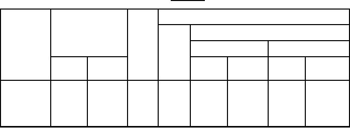
TABLE I. Style CV34.
Characteristics
Type
Capacitance
DC
designation
(pF)
rated
Symbol
Capacitance change from value at 25°C
voltage
(volts)
At -55°C
At +85°C
Minimum
Maximum
Minimum
Maximum
Minimum
Maximum
percent
Percent
percent
percent
+2.0
-2.5
+2.0
-4.5
A
350
8.0
1.5
CV34A080
+2.0
-2.5
+2.0
-4.5
A
350
15.0
4.0
CV34A150
-1.5
-5.0
+7.0
+1.5
D
200
20.0
4.0
CV34D200
-1.5
-5.0
+7.0
+1.5
D
200
35.0
8.0
CV34D350
-3.0
-10.0
+14.0
+3.0
E
500
60.0
15.0
CV34E600
Temperature coefficient: Within the limits specified for the applicable characteristics.
Capacitance drift: Within 0.75 percent of initial step 1 measurement or 0.50 (picofarad) pF, whichever is greater.
Terminal strength:
Pull test: Capacitor held by body and 4-pound load applied to each terminal for at least 10 seconds.
Torque: Not less than 1 ounce-inch nor more than 6 ounce-inches.
2