MIL-C-25/4E
NOTES:
1. See tables I and II for additional dimensions.
2. All dimensions in inches.
*
3. Metric equivalents are given for general information only.
4. Terminals need not be identified by numbers as shown. Shape of terminals and terminal lugs (drilled,
punched, forked, or slotted) optional.
5. Mounting holes may be elongated.
6. For circuit 1, use terminals 1 and 2. For circuit 2, use terminal 1. For circuit 4, use terminal 1 for
common connection and identify common terminal by the letter C on case adjacent to terminal. For
circuit 6, use terminals 1 and 2.
7. Capacitors differ only in location of terminals. Style CP53, having the terminals on one side, contains
certain values of capacitance in a smaller case than is possible with styles CP54 and CP55, the
terminals of which are on top and bottom faces, respectively.
8. Terminal lugs shall be oriented as shown with respect to side of case bearing terminal identification
numbers.
FIGURE 1. Styles CP53, CP54, and CP55 capacitors - Continued.
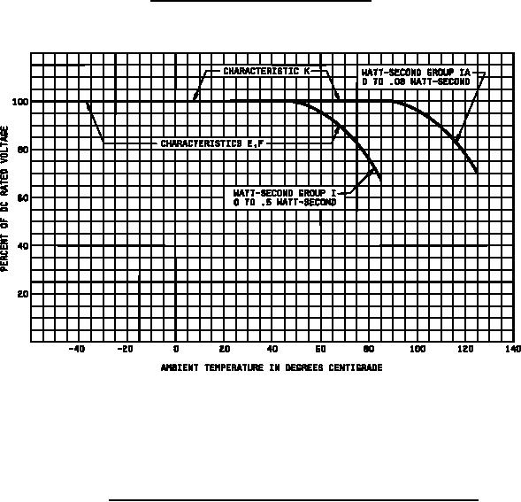
NOTE: Permissible operating voltages, while based on incomplete data are the capacitor suppliers' best estimate to
provide a life expectancy of 8,800 hours of continuous operation at higher ambient temperatures. Longer life can be
expected by operation at voltages lower than indicated on the curve: For example, a life expectancy of 44,000 hours
may be obtained by operation at 70 percent of the voltage determined by use of this curve. Also, a life longer than
8,800 hours may be expected at the voltage determined by use of this curve if the high ambient temperature prevails
for only a portion of the whole operating time.
FIGURE 2. Voltage derating for ambient temperature (characteristics E, F, and K).
4
For Parts Inquires submit RFQ to Parts Hangar, Inc.
© Copyright 2015 Integrated Publishing, Inc.
A Service Disabled Veteran Owned Small Business